

1/ Some terms, before:
OAM for Operations Administration and Maintenance
LFM for Link Fault Management
EFM for Ethernet in the First Mile
2/ Introduction:
OAM is intended for point-to-point or emulated p2p Ethernet links. The OAM block is optional, so it has to be compatible with Layer 2 device that do not support OAM LFM. In other words, between 2 routers interconnected with a p2p Ethernet link, one can support OAM LFM and the other one not. The Layer 2 of this one shouldn’t be impacted by OAM frames sent by its peer. OAM LFM discovers automatically via a discovery mechanism, OAM capabilities of neighbors. OAM frames are also inhibited by the MAC Control PAUSE mechanism (aka Flow Control).
OAM Modes:
As LACP, there are 2 modes for the OAM client. Active and Passive. The following tab resumes the behaviour of Active and Passive mode routers:
Note: Only Active clients can initiate discovery mode, and also send remote loopback control. In other words, Active client does not take into account loopback messages coming from a Passive client. On a given p2p link, only one OAM client as to be in Active mode to auto-discovery neighbor’s capabilities.

OAM is intended for point-to-point or emulated p2p Ethernet links. The OAM block is optional, so it has to be compatible with Layer 2 device that do not support OAM LFM. In other words, between 2 routers interconnected with a p2p Ethernet link, one can support OAM LFM and the other one not. The Layer 2 of this one shouldn’t be impacted by OAM frames sent by its peer. OAM LFM discovers automatically via a discovery mechanism, OAM capabilities of neighbors. OAM frames are also inhibited by the MAC Control PAUSE mechanism (aka Flow Control).
OAM Mode:
As LACP, there are 2 modes for the OAM client. Active and Passive. The following tab resumes the behaviour of Active and Passive mode routers:
Note: Only Active clients can initiate discovery mode, and also send remote loopback control. In other words, Active client does not take into account loopback messages coming from a Passive client. On a given p2p link, only one OAM client as to be in Active mode to auto-discovery neighbor’s capabilities.

OAM Events:
Some events can interact with the OAM state machine. We can notice:
- Critical events: 3 pre-defined events: Link fault, Dying gasp and Critical events. These 3 “states” are implementation specific. The consequence of receiving one of them is to shutdown the layer 2. For Junos: link down state. Dying gasp is usually internal error and the Critical event referred to a “fatal error” (like hard and soft failure). This unexpected errors are conveyed by OAM PDU.
- Link events: Link events includes Framing Errors or Symbol Errors. A client generates local link event when for example the received framing errors threshold is reached. It refers to BDI: inform upstream client that errors have occurred on the local receive path. The consequence of receiving this kind of event is generally configurable. For Junos, you can select one or more actions: Syslog, Link down, sending back Critical Event.
OAM PDU:
OAM PDU are conveyed directly within Ethernet frames. OAM Frames are never flooded, they have a link local scope. Ethernet frames that carry OAM PDU use 01:80:C2:00:00:02 for destination address (the same as LACP). The EtherType field is equal to 0x8809 (slow protocol, as LACP). The distinction of LACP and OAM frames is done by the subtype field, first mandatory byte for Slow Protocol based present just after the EtherType Field. A value of 0x03 is for OAM frames, 0x01 is reserved for LACP frames. Hereafter the wireshark capture of the OAM header.

The “flags” field is very important because it conveys both Critical Events flags and State Machine Information used during the discovery phase. The following byte called OAM PDU code, provides information regarding OAM data carried by TLVs. Code may be:
- 0x00 Information (using discovery phase and then during keepalive)
- 0x01 Event notification (convey Link Event information to inform remote peer of a local link event).
- 0x02-0x03 Respectively Variable request and response (for MIB polling) (not cover by this presentation).
- 0x04 Loopback control information.
OAM Discovery phase:
Only Active OAM client initiates the discovery phase. The “flags” field informs each side of the Local and Remote state and the code field is always 0x00 during this phase. At the end of the discovery process, each side has to be in “discovery complete” state. After that, periodic OAM Information are sends as a keepalive mechanism, to detect unexpected OAM client failure (aka: neighbor failure detection).
I’ve re-designed the OAM Discovery State Diagram of the 802.3ah document, just to better understand step by step this important phase.

By default OAM LFM client sends periodic PDU every 1 sec. The FAULT state is the “begin” state or the state directly selected if the LFM “adjacency” holdtime expired (by default 5s) or if a link failure occurred.
If the LINK is UP/UP and there is no error, the OAM client moves to the ACTIVE SEND LOCAL state or PASSIVE WAIT state depending of the configured mode. In PASSIVE mode, the client waits to receive an OAM PDU information with the LOCAL EVALUATING flag set to 1. In ACTIVE mode, the OAM client sends periodic OAM PDU that carry only the LOCAL INFORMATION TLV. It set also the LOCAL EVALUATING flag to 1 and the LOCAL STABLE flag to 0 (it means: the discovery is in progress).
Note: The REMOTE EVALUATING and REMOTE STABLE flags have to be a copy of the LOCAL EVALUATING and LOCAL STABLE flags of the remote peer (received from the OAM PDU of the remote peer).

So in this case if we consider that the router R1 is the first to send the first OAM PDU, REMOTE EVALUATING and REMOTE STABLE flags are set to zero.
Hereafter the wireshark capture of the OAM PDU sent at this step.
ACTIVE SEND LOCAL OAM PDU PCAP :

The TLV Local Information carries the mode of the Local OAM Client and the State of the Parser and Mux state machine (OAM sub-layer is transparent for other frames: no blocking state) and finally the Local capabilities of the OAM client (hard coded or configured). In my case, I’ve just configured the LINK EVENT support but not the loopback mode.
Next step, in ACTIVE mode the client sends the above message every pdu_timer until the client receives an OAM PDU information with the LOCAL EVALUATING flag set to 1. When this state is reached the OAM CLIENT enters in the SEND LOCAL REMOTE state. In my example, the router R2 is already in the ACTIVE SEND LOCAL state, it receives the OAM PDU info from R1 but has not yet sent its own OAM PDU that conveys its local state. So, the R2 router sends an OAM PDU information with its local state and the LOCAL EVALUATING flag set to 1 and a copy of the remote LOCAL flag in its REMOTE flags (so REMOTE EVALUATING is set to 1). R2 then enters in the SEND LOCAL REMOTE state, unlike R1 that stays in ACTIVE SEND LOCAL state because it has not yet received the OAM PDU info from R2.

When R1 receives the OAM PDU info from R2 it enters in SEND LOCAL REMOTE state as well. In this step, the 2 routers must send Local and Remote TLV information.

After that each router checks if Local and Remote information are compatible. If yes, the OAM client enters in the SEND LOCAL REMOTE OK state. The internal state is local_stable is set to TRUE. This means, at the OAM PDU level, LOCAL EVALUATING flag set to 0 and LOCAL STABLE set to 1 (discovery complete).
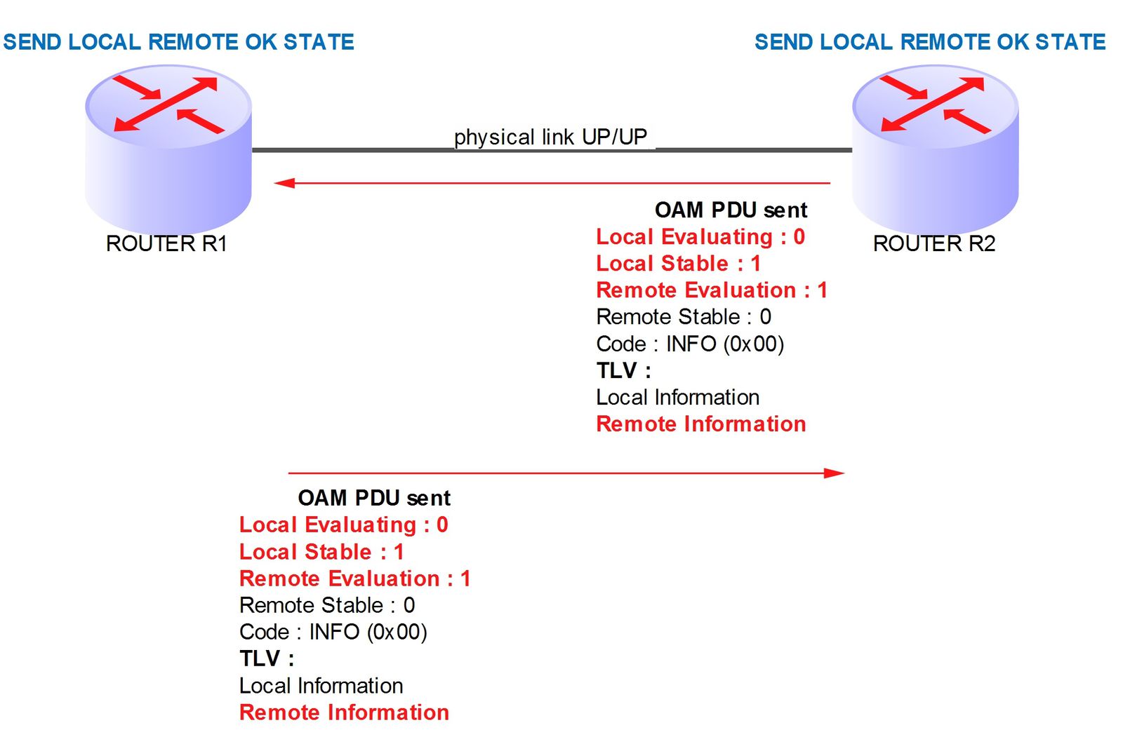
Finally when the OAM client receives the OAM PDU of its remote peer with LOCAL STABLE at 1, it moves tothe final step : SEND ANY state.

At this step, the discovery is complete, the OAM client still sends periodic OAM PDU information to keep the LFM “adjancency” UP and track some neighbor timeout events. Remember, at each step if local and remote changes occurred the OAM client can go back to previous state or in case of link failure or receiving critical event moves directly to the FAULT state.
Below, a wireshark capture of periodic OAM PDU sends after the discovery stage.

Remote Loopback operation:
Remote Loopback capability allows a router to force its remote peer to place its interface in loopback mode. In other words, all frames except OAM PDU received by the remote peer will be loop back without any changing. So, put in loopback mode an interface stops forwarding and cuts all neighbor relationships on this interface. Only OAM LFM adjacency stays UP. So this mode is for troubleshooting purposes.
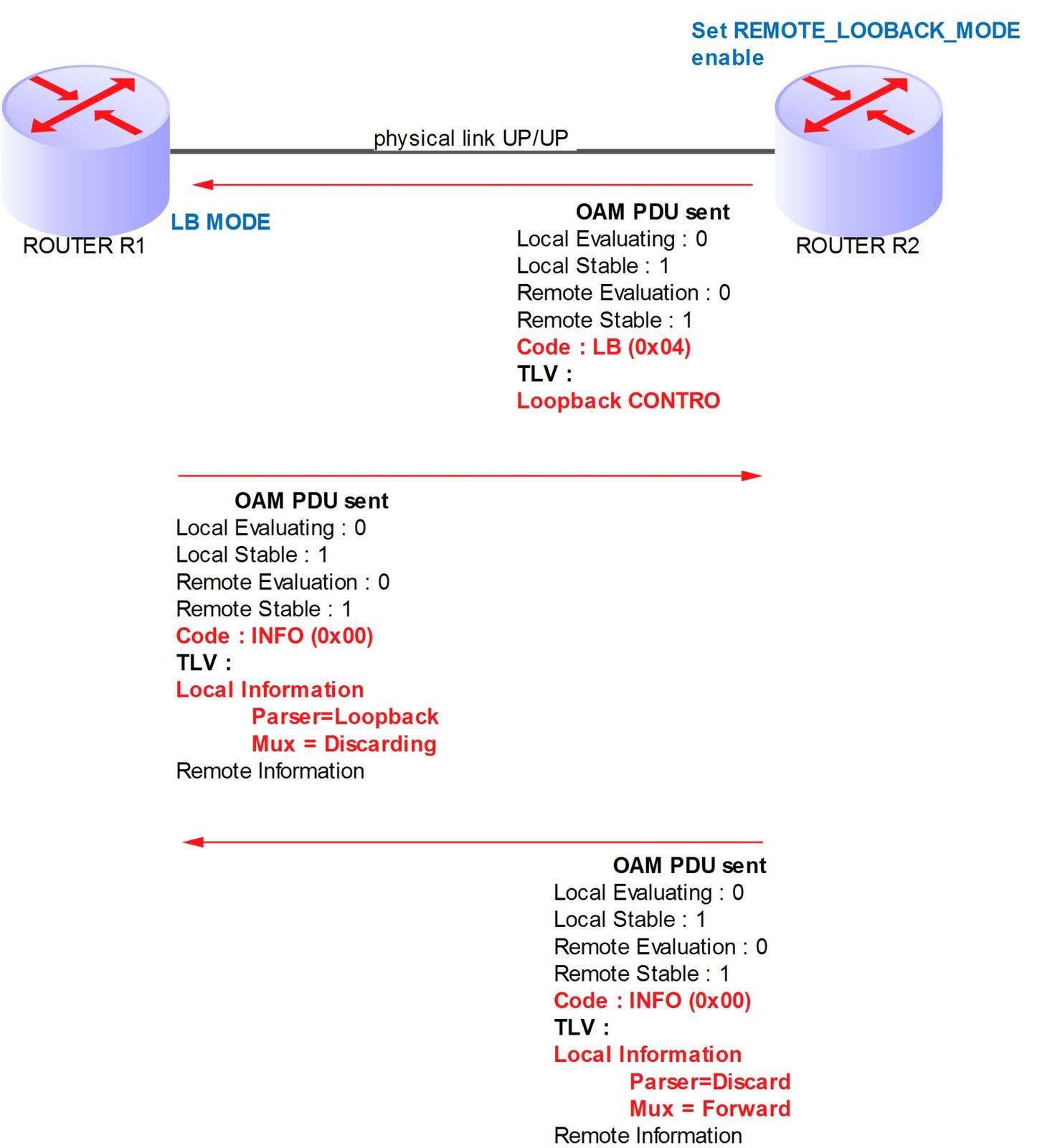
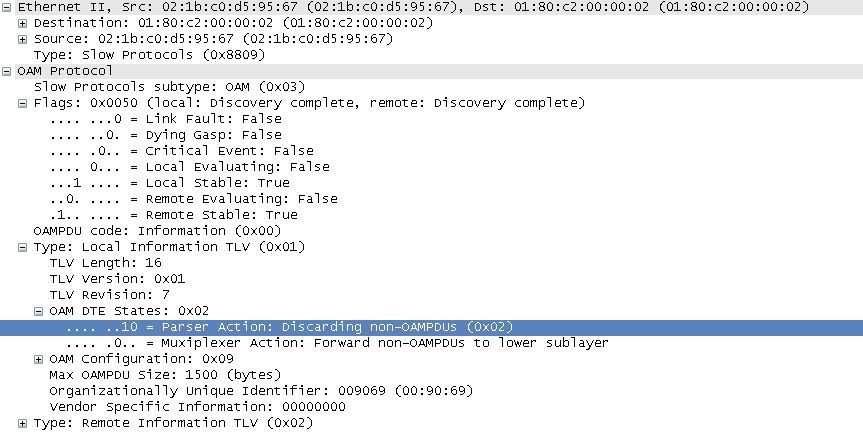
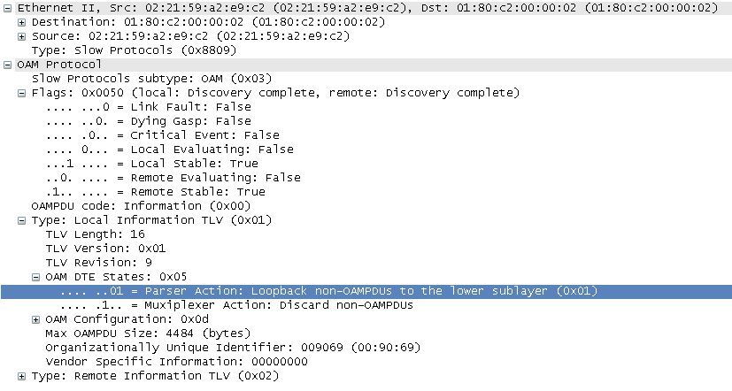
For the above case, we explicitly set the REMOTE_LOOPBACK_MODE on R2. This configuration triggers the sending of a loopback control OAM PDU (code 0x04) from R2 to R1. So, R1 moves in loopback mode. R1 updates its LOCAL INFORMATION by setting its Parser state at Loopback and its Mux state in DISCARDING state. In parallel, R2 updates its Parser state in Discarding state and keep its Mux in forwarding state.
Parser is responsible of received MAC frames
Mux is responsible of sent MAC frames.
The following Wireshark captures show this sequence of messages :
R2 to R1:

Then R1 to R2:

And then R2 to R1:
OAM Link Events:
This kind of events are triggered when a Local OAM client detects that the percentage of received frames (not OAM PDU but the real Ethernet traffic) are in error, and that the configured threshold for these errors is reached. There are 4 kinds of Link Event messages, but only 2 types of error are monitored: the symbol error and the framing error. The first concerns the physical layer 1 (each symbol conveys several bits) and the second one concerns the layer 2 and includes these types of errors:
- Frame Too Long error : indicates that the last frame received had a frameSize beyond the maximum allowable frame size.
- Frame Check Error indicates that the frame received was damaged by a transmission error (aka. FCS error).
- Length Error: indicates that the lengthOrTypeParam value was both consistent with a length interpretation of this field (i.e., its value was less than or equal to maxValidFrame), and inconsistent with the frameSize of the received frame.
- Alignment Error: indicates that the frame received was damaged, and that in addition, its length was not an integer number of octets.
An event is generated locally based on the received frames stats (statistics gathered at the Layer 1 and Layer 2) and the locally configured thresholds. This event triggers an action locally (syslog, link down) and the sending of an OAM PDU link event to inform the remote peer (aka. RDI).
The 4 link event messages are conveyed within OAM PDU frames with the code 0x01 and each one has a specific TLV:
- Errored Symbol Period Event TLV. Provide the number of Layer 1 symbol errors that occurring during the specific period (called window). The TLV has the following fields:
o Event Time Stamp: In “tick” of 100ms. It represents the time reference when the event was generated.
o Errored Symbol Window: represents the number of symbols in the period for the physical layer (in depends of the rate of the link and the type of coding (ie. 64b/66b PCS)). Default is number of symbols during one second.
o Errored Symbol Threshold: number of errored symbols in the period required to remotely generated this event. Default is 1 symbol.
o Errored Symbols: number of symbols errors in the period.
o Error Running Total: number of symbol errors since the OAM sublayer was reset.
o Event Running Total: number of this kind of event generated since the OAM sublayer was reset.
- Errored Frame Event TLV. Provide the number Ethernet framing errors that occurring during the specific period (called window). The period is specified by a time interval. The TLV has the following fields:
o Event Time Stamp: In “tick” of 100ms. It represents the time reference when the event was generated.
o Errored Frame Window: represents the period in term of 100ms intervals (default is one second so a value of 10).
o Errored Frame Threshold: number of errored frames in the period required to remotely generated this event. Default is 1 frame.
o Errored Frame: number of detected framing errors in the period.
o Error Running Total: number of framing error since the OAM sublayer was reset.
o Event Running Total: number of this kind of event generated since the OAM sublayer was reset.
- Errored Frame Period Event TLV. Provide the number Ethernet framing errors that occurring during the specific period (called window). The period is specified by a number of received frames. The TLV has the following fields:
o Event Time Stamp: In “tick” of 100ms. It represents the time reference when the event was generated.
o Errored Frame Window: represents the number of frame (with the minimum size) that can be received during the period. Default, number of frames during one seconds
o Errored Frame Threshold: number of errored frames in the period required to remotely generated this event. Default is 1 frame.
o Errored Frame: number of errored frames in the period.
o Error Running Total: number of framing error since the OAM sublayer was reset.
o Event Running Total: number of this kind of event generated since the OAM sublayer was reset.
- Errored Frame Second Summary Event TLV. Provide the number Ethernet framing errors per second that occurring during the specific period (called window). The period is specified by a time interval. The TLV has the following fields:
o Event Time Stamp: In “tick” of 100ms. It represents the time reference when the event was generated.
o Errored Frame Window: represents the period in term of 100ms intervals (default is 60 seconds so a value of 600).
o Errored Frame Threshold: number of errored frames per second in the period required to remotely generated this event. Default is 1 frame.
o Errored Frame: number of detected framing errors per second in the period.
o Error Running Total: number of framing error per second since the OAM sublayer was reset.
o Event Running Total: number of this kind of event generated since the OAM sublayer was reset.
Now we can take the following example, R1/R2 link is a 10GE link. R2 detects a number of errored symbols during a specified period of 5 seconds (threshold is one). It triggers a local link event and then sends an OAM PDU Link Event (code 0x01) with the TLV Errored Symbol Period Event.

Hereafter a wireshark sample:

NEXT ???
Part 2 will present how to configure and troubleshoot OAM LFM (discovery, loopback, Link event) on JUNOS.
David


