I spent time on Junos routers (T and MX series) to understand how multicast replication works. I carried out some tests in lab to better understand how the multicast replication is done at the PFE level. This study was very useful for some multicast issues that I experienced in my operational network. The aim of this post is to share with you what I guess understand 
Patent search engines are usually good tools to obtain technical information. For this subject I've found 2 patents written by Juniper guys that provided me a lot of relevant information:
- Patent US 7,710,963: Binary Trees for multicast traffic
- Patent US 7,263,099: Multicast Packet replication
Note : I use some PFE commands that are not supported by the JTAC. Although I've never encountered an issue with these given commands (even on operational nodes), be carreful with them
1/ Basic information
Multicast replication, on Junos, is done at PFE (Packet Forwarding Engine) level. PFE is the entity within the linecard (FPC, DPC, MPC...) that manages : packet handling, route lookup, CoS, packet encapsulation, packet forwarding...
On a given card, there are more than one PFE. Each PFE supports more or less traffic and "connects" one or more physical ports. For instance :
- FPC 3 on T640 : 2 PFE (each PFE supports 20Gbits/s and connects 2x10GE links or 20x1GE links)
- FPC 4 on T1600 : 2 PFE (each PFE supports 40Gbit/s and connects for example 4x10GE PIC)
- DPCE 4x10GE on MX960 : 4 PFE (each PFE supports 10Gbits/s and connects 1x10GE link)
- MPC 3D 16x10GE on MX960 : 4 PFE (each PFE supports 30Gbits/s and connects 4x10GE links)
...
2/ PFE numbering
On a given slot, PFE are numbered from 0 to X from the top to the bottom (exception for DPCE 40x1GE). For example for the DPCE 4x10GE. The PFE #0 connects the link xe-x/0/0, PFE #1 xe-x/1/0, PFE #2 xe-x/2/0 and PFE #3 xe-x/3/0
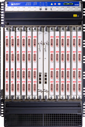
On a given chassis, PFE are numbered form 0 to N (where N is the maximum number of PFE in a chassis). For a current MX960 chassis we can have at most 12 Linecards of 4 PFE. So, N = 12x4 -1 = 47. So for an MX960, PFE are numbered from the left top (linecard 0) to the right bottom (Linecard 11). For example, a DPCE 4x10GE installed into the slot 4, has its PFE numbered (at the chassis level) : PFE #12 for the link xe-4/0/0, PFE #13 for the link xe-4/1/0, PFE #14 for the link xe-4/2/0, PFE #15 for the link xe-4/3/0. See the diagram below :
3/ Multicast Next-hop
On Junos, a multicast next-hop is an Indirect next-hop that represents for a given multicast stream (S;G) (S= Source , G= Group) the OIL : Outgoing Interface List (the replication tree). Find below an example :
Note : multicast routes are also available in the inet.1 table.
show multicast route group 232.0.1.1
Family: INET
Group: 232.0.1.1
Source: 10.1.1.1/32
Upstream interface: xe-4/0/1.0
Downstream interface list: <------ This is the OIL
xe-3/0/2.0 xe-3/1/1.0 xe-6/1/0.0 xe-6/0/3.0
For the stream (10.1.1.1,232.0.1.1) the stream received by the RPF (Reverse Path Forwarding) interface xe-4/0/1.0 will be replicated to 4 interfaces (listed in the OIL). The OIL could be the same for another (S;G) (it will depend of the multicast subscriptions received on the downstream interfaces).
To see the multicast Next-hop ID of a given stream, use the detail keyword :
show multicast route group 232.0.1.1 detail
Family: INET
Group: 232.0.1.1
Source: 10.1.1.1/32
Upstream interface: xe-4/0/1.0
Downstream interface list:
xe-3/0/2.0 xe-3/1/1.0 xe-6/1/0.0 xe-6/0/3.0
Session description: Source specific multicast
Statistics: 419 kBps, 308 pps, 227637824 packets
Next-hop ID: 1049784
Upstream protocol: PIM
As I said previously, an Indirect Multicast Next-hop represents a given OIL. You can see how many multicast next-hops are used and how many streams are associated to each Next-hop :
show multicast next-hops
Family: INET
ID Refcount KRefcount Downstream interface
1048927 4 2 xe-2/1/0.0
1048956 2 1 xe-2/1/0.0
xe-2/1/3.0
1048631 2 1 xe-2/1/0.0
xe-2/1/3.0
xe-3/1/0.0
1049784 6 3 xe-3/0/2.0
xe-3/1/1.0
xe-6/1/0.0
xe-6/0/3.0
For each Next-hop ID we have the detail of the OIL and the number of streams that use this OIL (Krefcount). For our previous example we have 3 (S,G) that have the same OIL, therefore the same replication tree. To resolve the indirect next-hop I query the forwarding table :
show route forwarding-table multicast destination 232.0.1.1
Routing table: default.inet
Internet:
Destination Type RtRef Next hop Type Index NhRef Netif
232.0.1.1.10.1.1.1/64
user 0 indr 1049784 4
mcrt 5481 1
The multicast "real" next-hop is 5481 at the PFE level. This one points to a Mcast replication list ID (we will see later).
4/ Binary Tree
The 2 patents gave me a lot of info regarding the replication algorithm. I knew that each PFE can replicate at most twice a stream. In other words, a PFE that receives an stream (S;G) can replicate the stream for all its directly connected interfaces (Local replications) and at most for 2 other PFEs. Note : in this configuration the internal links (HSL) between the PFE and the fabric might be oversubcribed by multicast.
Hereafter an example of a what we call a MULTICAST DUAL BINARY TREE. The binary tree is filled from the top to the botom and from the left to the right.

The root PFE is the PFE that receives the Stream: the PFE that hosts the RPF Interface (that can have also local replications). Leaves PFEs are PFE that do not have to replicate a stream to other PFEs (ie. PFE 9 and 10). Non leaf PFE is a PFE that has to replicate a stream to other PFEs (ie. PFE 6 and 12).
With this algorithm we do not ensure that a PFE replicates at most twice a stream. Indeed, if the PFE #6 is the ingress PFE (the ROOT) , this one has to send twice the stream through the Fabric toward PFE #6 (itself) and PFE #12 and then PFE#6 has to replicate in the 2nd tier, to PFE #9 and PFE #10. Therefore, PFE #6 replicates 4 times the stream. To avoid this, the Juniper patent says : To ensure at most 2 replications per PFE, the ingress PFE has to be a Leaf PFE. But with one single instance of the binary tree we can't do that. So Juniper purposes to have for each Multicast Next-hop : 2 instances of the Binary tree, the first one like the diagram above, and the second one computed from the first one but in a reverse sequential order. With this 2 instances of binary tree, we still have one binary tree that has any PFE as a leaf PFE.
So when a PFE receives a multicast stream and is therefore selected as the ROOT PFE, the first step is to select the right instance of the binary tree. In other words, the instance where the ROOT PFE is a leaf. If the ingress PFE is not included in the 2 instances, so it meams that there is no local replication for the ROOT PFE, the ROOT PFE selects the first instance.
Hereafter, the modified example :

As I said, if PFE#14 is the Ingress PFE, this PFE will select the instance 1 of the binary tree because this PFE does not have local replication so it does not appear in the binary tree. If PFE #9 or PFE #10 are the Ingress PFE, these PFE will select the instance 1, because only in this instance PFE #9 or PFE #10 are a leaf PFE. Finally if PFE #6 or PFE #12 are the Ingress PFE, then PFE will select instance 2 of the binary tree, to avoid more that 2 PFE replications for the PFEs.
5/ How to compute the tree
The other patent gives interresting info but I can applicate the given algo to my setup.
As we seen previously, the binary tree is the result of the multicast replication list : the OIL.
Each PFE use the same algorithm so the Dual Binary Tree for a given OIL (Multicast Next-hop) will be the same on each PFE.
From the OIL, the PFE derives the list of the PFE. In our first example the OIL was : xe-3/0/2.0 xe-3/1/1.0 xe-6/1/0.0 xe-6/0/3.0
Note : The chassis, for this example, is a T1600 with Sauza cards, on a T1600 there are 2 PFEs per FPC. Each Sauza PIC connected to a PFE hosts 4 10GE links. We can have 2 Sauza cards per FPC.
From the OIL, we find the PFE list (Chassis numbering) PFE #6, PFE #7, PFE #13, PFE #12. Here, we have the same number of entry in the PFE list than the number of Interfaces in the OIL (but this is not always the case). Then the PFE sorts the PFE list : (6; 7; 12 ; 13). To avoid continually starting the packet replication at the same entry (in our case PFE 6) an algorithm is used to randomize the starting point. The algo provided by one of the patents (based on the IFL ID of the RPF Interface) seems not fully implemented in Junos. Some infos missing.
So the algo selects the starting PFE : the PFE at the left of the tier 2. Then, the rest of the entries (in the sorted PFE list) populates the binary tree horizontally from the tier 2 to tier X. Upon reaching the end of the PFE list, the next node may correspond to the PFE at the beginning of the list until we reach the starting PFE.
In our example we suppose that the starting PFE selected by the algo is PFE #13. So each PFE computes the first instance of the binary tree and the reserve one (the second instance). The result for our case will be:

In our case the first instance will be used, because Ingress PFE is PFE #8 that does not have Local Replication : Indeed, Ingress interface is xe-4/0/1.0.
6/ Troubleshooting the tree for LMNR and Ichip architectures
I take again the following example (the dual binary tree is above - part 5) :
show multicast route group 232.0.1.1 detail
Family: INET
Group: 232.0.1.1
Source: 10.1.1.1/32
Upstream interface: xe-4/0/1.0
Downstream interface list:
xe-3/0/2.0 xe-3/1/1.0 xe-6/1/0.0 xe-6/0/3.0
Session description: Source specific multicast
Statistics: 419 kBps, 308 pps, 227637824 packets
Next-hop ID: 1049784 --> Resolved in 5481
Upstream protocol: PIM
The Ingress PFE is the PFE#8 hosted by the FPC 4 (xe-4/0/1.0). So let's go to the FPC 4 :
start shell pfe network fpc4
Now taking more info regarding the multicast next-hop 5481 the Mcast NH associated to the Indirect NH.
(vty)# show nhdb id 5481 detail
ID Type Interface Next Hop Addr Protocol Encap MTU
----- -------- ------------- --------------- ---------- ------------ ----
5481 MultiRT - - IPv4 - 4470
xe-3/0/2.0 IPv4 Ethernet
xe-3/1/1.0 IPv4 Ethernet
xe-6/1/0.0 IPv4 Ethernet
xe-6/0/3.0 IPv4 Ethernet
Nexthop Status:
Index: 5481 (0x1569), Slot: Unspecified
Destination (0x200): Multicast Chip9
Topo link: 0x00000000:0x4a6df201 0x00000000:0x4a996201
Refcount: 1, Interface: 0, Nexthop Flags: 0x0
RE IFL List index: 89
Have a look to the previous diagram (part 5) at each step.
Now we can check the Dual binary tree associated to the mcast replication list 89 (see below). As we can see there are 2 instances. The first one is used. The ingress PFE is the PFE #8 (chassis level) but for the FPC point of view this is the PFE #0.
The terms r1 and r2 are, I guess, Replication 1 and Replication 2 (the 2 downstream PFE for the tier 1 so used by the ROOT only), f1 and f2, I guess are Downstream PFE for the other tiers). The nl flag is, I guess again, means “leaf node” (see patent) and for me has a meaning only for tier 2 and more (only when we use f1 and f2)
So the PFE #8 has to replicate to PFE #13 and PFE #6 (we use r1 and r2 because PFE#8 is the ROOT PFE in the tier 1). I guess nl is always equal to 1 for the Ingress PFE.
(vty)# show nhdb mcast tables
FE Multicast trees for proto(IPv4) :
idx total FE address list
--- ----- ------------------------------------------------
82 3 12 5, 7
7 5, 12
89 4 13 6, 7 12 <<< instance 1 (used)
12 7, 6 13 <<< instance 2 (reverse one)
90 3 6 9, 11
11 9, 6
Multicast list for PFE 0 (8), proto(IPv4) :
idx r1 r2 f1 f2 nl total single strm idx(chip/strm id)
--- -- -- -- -- -- ----- -----------------------------
82 12 5 1 0
89 13 6 1 0
90 6 9 1 0
--- -- -- -- -- -- ----- -----------------------------
Multicast list for PFE 1 (9), proto(IPv4) :
idx r1 r2 f1 f2 nl total single strm idx(chip/strm id)
--- -- -- -- -- -- ----- -----------------------------
82 12 5 1 0
89 13 6 1 0
90 6 9 1 2 1/13 1/15
In BLUE : PFE numbering at FPC level
In Red : PFE numbering at Chassis Level
Now, go on to the next PFE of the tree (tier 2) : PFE #13 on FPC 6.
The PFE #13 is not a leaf PFE (nl = 0) , so it has to replicate the stream to PFE #7 (f1) and PFE #12 (f2). Here PFE #13 has one local replication. To resolve the local replication (to have the interface name) use the Local Per Stream IFL List, that gives us the IFL of the interface. Then resolve the IFL : cool ! this is xe-6/1/0.0 (one downstream interface of the OIL)
start shell pfe network fpc6
(vty)# show nhdb mcast tables
FE Multicast trees for proto(IPv4) :
idx total FE address list
--- ----- ------------------------------------------------
82 3 12 5, 7
7 5, 12
89 4 13 6, 7 12 <<< instance 1 used
12 7, 6 13
90 3 6 9, 11
Multicast list for PFE 0 (12), proto(IPv4) :
idx r1 r2 f1 f2 nl total single strm idx(chip/strm id)
--- -- -- -- -- -- ----- -----------------------------
82 7 5 7 0 2 0/1 0/0
89 13 6 6 13 1 1 0/0
90 6 9 1 0
Multicast list for PFE 1 (13), proto(IPv4) :
idx r1 r2 f1 f2 nl total single strm idx(chip/strm id)
--- -- -- -- -- -- ----- -----------------------------
82 12 5 1 0
89 12 7 7 12 0 1 1/0 à See below the “Local Per Stream lists”
90 6 9 1 0
Local Per Stream IFL lists:
chip stream index ref address List
---- ------ ----- --- -------- ------
0 48 0 35 0x0000a4 105
0 32 1 34 0x0000a8 104
1 0 0 29 0x00000c 103 à IFL of the Local replication
In BLUE : PFE numbering at FPC level
In Red : PFE numbering at Chassis Level
(vty)# show ifl 103
Logical interface xe-6/1/0.0 (Index 103, Alias-Index 0 Peer-Index 0)
Now, go on to the next PFE of the tree (tier 2) : PFE # 6 on FPC 3.
The PFE #6 is a leaf PFE (nl = 1), so f1 and f2 are not used and PFE replication stops. Here PFE #6 has one local replication. To resolve the local replication (to have the interface name) use the Local Per Stream IFL List, that gives us the IFL of the interface. Then resolve the IFL : this is xe-3/0/2.0 (another downstream interface of the OIL)
start shell pfe network fpc3
(vty)# show nhdb mcast tables
FE Multicast trees for proto(IPv4) :
idx total FE address list
--- ----- ------------------------------------------------
82 3 12 5, 7
7 5, 12
89 4 13 6, 7 12 <<< instance 1 used
12 7, 6 13
90 3 6 9, 11
11 9, 6
Multicast list for PFE 0 (6), proto(IPv4) :
idx r1 r2 f1 f2 nl total single strm idx(chip/strm id)
--- -- -- -- -- -- ----- -----------------------------
82 12 5 1 0
89 13 6 1 1 0/1 à See below the “Local Per Stream lists”
90 11 9 11 0 1 0/1
--- -- -- -- -- -- ----- -----------------------------
Multicast list for PFE 1 (7), proto(IPv4) :
idx r1 r2 f1 f2 nl total single strm idx(chip/strm id)
--- -- -- -- -- -- ----- -----------------------------
82 12 5 12 1 1 1/3
89 13 6 1 1 1/1
90 6 9 1 0
--- -- -- -- -- -- ----- -----------------------------
Local Per Stream IFL lists:
chip stream index ref address List
---- ------ ----- --- -------- ------
0 48 0 41 0x0001a0 78
0 32 1 39 0x0001a4 77 à IFL of the Local replication
1 0 0 40 0x0000fc 79
1 16 1 29 0x000100 81
1 32 2 29 0x000104 80
1 48 3 36 0x000108 82
In BLUE : PFE numbering at FPC level
In Red : PFE numbering at Chassis Level
(vty)# show ifl 77
Logical interface xe-3/0/2.0 (Index 77, Alias-Index 0 Peer-Index 0)
Now, go on to the next PFE of the tree (tier 3) : PFE #7 on FPC 3.
The PFE #7 is a leaf PFE (nl = 1), therefore f1 and f2 are not used and PFE replication stops. Here PFE #7 has one local replication. To resolve the local replication (to have the interface name) use the Local Per Stream IFL List, that gives us the IFL of the interface. Then resolve the IFL : this is xe-3/1/1.0 (another downstream interface of the OIL)
start shell pfe network fpc3
(vty)# show nhdb mcast tables
FE Multicast trees for proto(IPv4) :
idx total FE address list
--- ----- ------------------------------------------------
82 3 12 5, 7
7 5, 12
89 4 13 6, 7 12 <<< instance 1 used
12 7, 6 13
90 3 6 9, 11
11 9, 6
Multicast list for PFE 0 (6), proto(IPv4) :
idx r1 r2 f1 f2 nl total single strm idx(chip/strm id)
--- -- -- -- -- -- ----- -----------------------------
82 12 5 1 0
89 13 6 1 1 0/1
90 11 9 11 0 1 0/1
--- -- -- -- -- -- ----- -----------------------------
Multicast list for PFE 1 (7), proto(IPv4) :
idx r1 r2 f1 f2 nl total single strm idx(chip/strm id)
--- -- -- -- -- -- ----- -----------------------------
82 12 5 12 1 1 1/3
89 13 6 1 1 1/1 à See below the “Local Per Stream lists”
90 6 9 1 0
--- -- -- -- -- -- ----- -----------------------------
Local Per Stream IFL lists:
chip stream index ref address List
---- ------ ----- --- -------- ------
0 48 0 41 0x0001a0 78
0 32 1 39 0x0001a4 77
1 0 0 40 0x0000fc 79
1 16 1 29 0x000100 81 à IFL of the Local replication
1 32 2 29 0x000104 80
1 48 3 36 0x000108 82
In BLUE : PFE numbering at FPC level
In Red : PFE numbering at Chassis Level
(vty)# show ifl 81
Logical interface xe-3/1/1.0 (Index 81, Alias-Index 0 Peer-Index 0)
Finally, go on to the last PFE of the tree (tier 3) : PFE #12 on FPC 6.
The PFE #12 is a leaf PFE (nl = 1), therefore f1 and f2 are not used and PFE replication stops. Here PFE #12 has one local replication. To resolve the local replication (to have the interface name) use the Local Per Stream IFL List, that gives us the IFL of the interface. Then resolve the IFL : this is xe-6/0/3.0 (the last downstream interface of the OIL)
start shell pfe network fpc6
(vty)# show nhdb mcast tables
FE Multicast trees for proto(IPv4) :
idx total FE address list
--- ----- ------------------------------------------------
82 3 12 5, 7
7 5, 12
89 4 13 6, 7 12 <<< instance 1 used
12 7, 6 13
90 3 6 9, 11
Multicast list for PFE 0 (12), proto(IPv4) :
idx r1 r2 f1 f2 nl total single strm idx(chip/strm id)
--- -- -- -- -- -- ----- -----------------------------
82 7 5 7 0 2 0/1 0/0
89 13 6 6 13 1 1 0/0 à See below the “Local Per Stream lists”
90 6 9 1 0
Multicast list for PFE 1 (13), proto(IPv4) :
idx r1 r2 f1 f2 nl total single strm idx(chip/strm id)
--- -- -- -- -- -- ----- -----------------------------
82 12 5 1 0
89 12 7 7 12 0 1 1/0
90 6 9 1 0
Local Per Stream IFL lists:
chip stream index ref address List
---- ------ ----- --- -------- ------
0 48 0 35 0x0000a4 105 à IFL of the Local replication
0 32 1 34 0x0000a8 104
1 0 0 29 0x00000c 103
In BLUE : PFE numbering at FPC level
In Red : PFE numbering at Chassis Level
(vty)# show ifl 105
Logical interface xe-6/0/3.0 (Index 105, Alias-Index 0 Peer-Index 0)
Done.... 
7/ Troubleshooting the tree for TRIO architectures
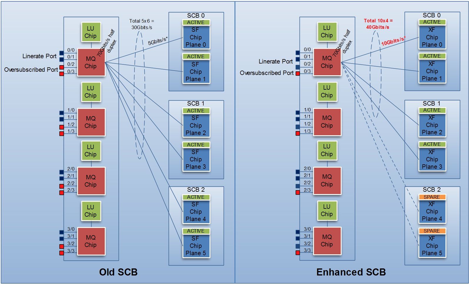
By default Trio cards use Dual binary Tree like DPC and FPC, but an enhanced feature allow the use of more bandwitdh between PFE and the Fabric. To use this enhanced feature you need to have only TRIO cards into the chassis and activate the feature via a chassis command.
Troubleshooting binary tree on Trio it is more complex (I have to do more tests in lab to better understand the command outputs). Nervertheless the following command seems to provide interresting info, with a "ascii binary tree". I will update this part soon.
show nhdb id 1769 detail --> 1769 is the resolved multicast nh
ID Type Interface Next Hop Addr Protocol Encap MTU Flags PFE internal Flags
----- -------- ------------- --------------- ---------- ------------ ---- ---------- --------------------
1769 Multi-RT - - IPv4 - 0 0x00000000 0x00000000
Mcast List Index: 26 ()
PFE#0, child#0 = 1776
mcast-tree:
nfes:5, hash:1
38, 8, 11, 23, 35,
Root
38 08
11 23 35
David.


